


RING NETWORK
A ring network is a network topology in which each node connects to exactly two other nodes, forming a single continuous pathway for signals through each node - a ring. Data travels from node to node, with each node along the way handling every packet.
Because a ring topology provides only one pathway between any two nodes, ring networks may be disrupted by the failure of a single link. A node failure or cable break might isolate every node attached to the ring. FDDI networks overcome this vulnerability by sending data on a clockwise and a counterclockwise ring: in the event of a break data is wrapped back onto the complementary ring before it reaches the end of the cable, maintaining a path to every node along the resulting "C-Ring". 802.5 networks -- also known as IBM Token Ring networks -- avoid the weakness of a ring topology altogether: they actually use a star topology at the physical layer and a Multistation Access Unit to imitate a ring at the datalink layer.
Many ring networks add a "counter-rotating ring" to form a redundant topology. Such "dual ring" networks include Spatial Reuse Protocol, Fiber Distributed Data Interface (FDDI), and Resilient Packet Ring.
Advantages
See also: Ring Protection
Very orderly network where every device has access to the token and the opportunity to transmit
Performs better than a star topology under heavy network load
Can create much larger network using Token Ring
Does not require network server to manage the connectivity between the computers
Disadvantages
One malfunctioning workstation or bad port in the MAU can create problems for the entire network
Moves, adds and changes of devices can affect the network
Network adapter cards and MAU's are much more expensive than Ethernet cards and hubs
Much slower than an Ethernet network under normal load
Misconceptions
"Token Ring is an example of a ring topology." 802.5 (Token Ring) networks do not use a ring topology at layer 1. As explained above, IBM Token Ring (802.5) networks imitate a ring at layer 2 but use a physical star at layer 1.
"Rings prevent collisions." The term "ring" only refers to the layout of the cables. It is true that there are no collisions on an IBM Token Ring, but this is because of the layer 2 Media Access Control method, not the physical topology (which again is a star, not a ring.) Token passing, not rings, prevent collisions.
"Token passing happens on rings." Token passing is a way of managing access to the cable, implemented at the MAC sublayer of layer 2. Ring topology is the cable layout at layer one. It is possible to do token passing on a bus (802.4) a star (802.5) or a ring (FDDI). Token passing is not restricted to rings.
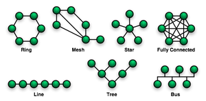 Network topology is the study of the arrangement or mapping of the elements (links, nodes, etc.) of a network, especially the physical (real) and logical (virtual) interconnections between nodes.[1][2] A local area network (LAN) is one example of a network that exhibits both a physical topology and a logical topology. Any given node in the LAN will have one or more links to one or more other nodes in the network and the mapping of these links and nodes onto a graph results in a geometrical shape that determines the physical topology of the network. Likewise, the mapping of the flow of data between the nodes in the network determines the logical topology of the network. The physical and logical topologies might be identical in any particular network but they also may be different.
Any particular network topology is determined only by the graphical mapping of the configuration of physical and/or logical connections between nodes. LAN Network Topology is, therefore, technically a part of graph theory. Distances between nodes, physical interconnections, transmission rates, and/or signal types may differ in two networks and yet their topologies may be identical.
Star network
 Star network layout
Star networks are one of the most common computer network topologies. In its simplest form, a star network consists of one central switch, hub or computer, which acts as a conduit to transmit messages.[1] Thus, the hub and leaf nodes, and the transmission lines between them, form a graph with the topology of a star. If the central node is passive, the originating node must be able to tolerate the reception of an echo of its own transmission, delayed by the two-way transmission time (i.e. to and from the central node) plus any delay generated in the central node. An active star network has an active central node that usually has the means to prevent echo-related problems.
The star topology reduces the chance of network failure by connecting all of the systems to a central node. When applied to a bus-based network, this central hub rebroadcasts all transmissions received from any peripheral node to all peripheral nodes on the network, sometimes including the originating node. All peripheral nodes may thus communicate with all others by transmitting to, and receiving from, the central node only. The failure of a transmission line linking any peripheral node to the central node will result in the isolation of that peripheral node from all others, but the rest of the systems will be unaffected. [2]Contents [hide]
Advantages
Star network layoutStar networks are one of the most common computer network topologies. In its simplest form, a star network consists of one central switch, hub or computer, which acts as a conduit to transmit messages.[1] Thus, the hub and leaf nodes, and the transmission lines between them, form a graph with the topology of a star. If the central node is passive, the originating node must be able to tolerate the reception of an echo of its own transmission, delayed by the two-way transmission time (i.e. to and from the central node) plus any delay generated in the central node. An active star network has an active central node that usually has the means to prevent echo-related problems.
The star topology reduces the chance of network failure by connecting all of the systems to a central node. When applied to a bus-based network, this central hub rebroadcasts all transmissions received from any peripheral node to all peripheral nodes on the network, sometimes including the originating node. All peripheral nodes may thus communicate with all others by transmitting to, and receiving from, the central node only. The failure of a transmission line linking any peripheral node to the central node will result in the isolation of that peripheral node from all others, but the rest of the systems will be unaffected. [2]Contents [hide]
Advantages
Better performance: Passing of Data Packet through unnecessary nodes is prevented by this topology. At most 3 devices and 2 links are involved in any communication between any two devices which are part of this topology. This topology induces a huge overhead on the central hub, however if the central hub has adequate capacity, then very high network utilization by one device in the network does not affect the other devices in the network.
Isolation of devices: Each device is inherently isolated by the link that connects it to the hub. This makes the isolation of the individual devices fairly straightforward, and amounts to disconnecting the device from the hub. This isolated nature also prevents any non-centralized failure from affecting the network.
Benefits from centralization: As the central hub is the bottleneck, increasing capacity of the central hub or adding additional devices to the star, can help scale the network very easily. The central nature also allows the inspection of traffic through the network. This can help analyze all the traffic in the network and determine suspicious behavior.
Simplicity: The topology is easy to understand, establish, and navigate. The simple topology obviates the need for complex routing or message passing protocols. As noted earlier, the isolation and centralization simplifies fault detection, as each link or device can be probed individually.
Disadvantages
The primary disadvantage of a star topology is the high dependence of the system on the functioning of the central hub. While the failure of an individual link only results in the isolation of a single node, the failure of the central hub renders the network inoperable, immediately isolating all nodes. The performance and scalability of the network also depend on the capabilities of the hub. Network size is limited by the number of connections that can be made to the hub, and performance for the entire network is capped by its throughput. While in theory traffic between the hub and a node is isolated from other nodes on the network, other nodes may see a performance drop if traffic to another node occupies a significant portion of the central node's processing capability or throughput. Furthermore, wiring up of the system can be very complex.

BUS NETWORK
A bus network topology is a network architecture in which a set of clients are connected via a shared communications line, called a bus. There are several common instances of the bus architecture, including one in the motherboard of most computers, and those in some versions of Ethernet networks.
Bus networks are the simplest way to connect multiple clients, but may have problems when two clients want to transmit at the same time on the same bus. Thus systems which use bus network architectures normally have some scheme of collision handling or collision avoidance for communication on the bus, quite often using Carrier Sense Multiple Access or the presence of a bus master which controls access to the shared bus resource.
A true bus network is passive – the computers on the bus simply listen for a signal; they are not responsible for moving the signal along. However, many active architectures can also be described as a "bus", as they provide the same logical functions as a passive bus; for example, switched Ethernet can still be regarded as a logical bus network, if not a physical one. Indeed, the hardware may be abstracted away completely in the case of a software bus.
With the dominance of switched Ethernet over passive Ethernet, passive bus networks are uncommon in wired networks. However, almost all current wireless networks can be viewed as examples of passive bus networks, with radio propagation serving as the shared passive medium.
The bus topology makes the addition of new devices straightforward. The term used to describe clients is station or workstation in this type of network. Bus network topology uses a broadcast channel which means that all attached stations can hear every transmission and all stations have equal priority in using the network to transmit.
Advantages and disadvantages of a bus network
Advantages
Easy to implement and extend
Well suited for temporary or small networks not requiring high speeds (quick setup)
Cheaper than other topologies.
Cost effective as only a single cable is used
Cable faults are easily identified.
Weight reduction due to less wires
Disadvantages
Limited cable length and number of stations.
If there is a problem with the cable, the entire network goes down.
Maintenance costs may be higher in the long run.
Performance degrades as additional computers are added or on heavy traffic.
Proper termination is required (loop must be in closed path).
Significant Capacitive Load (each bus transaction must be able to stretch to most distant link).
It works best with limited number of nodes.
It is slower than the other topologies.
Standing Wave: As in bus topology there is necessity of proper termination if there is no termination the waves get reflected at the ends and gets added in other incoming waves causing cancellation. this addition and cancellation of waves leads to a standing wave.


0 comments:
Post a Comment